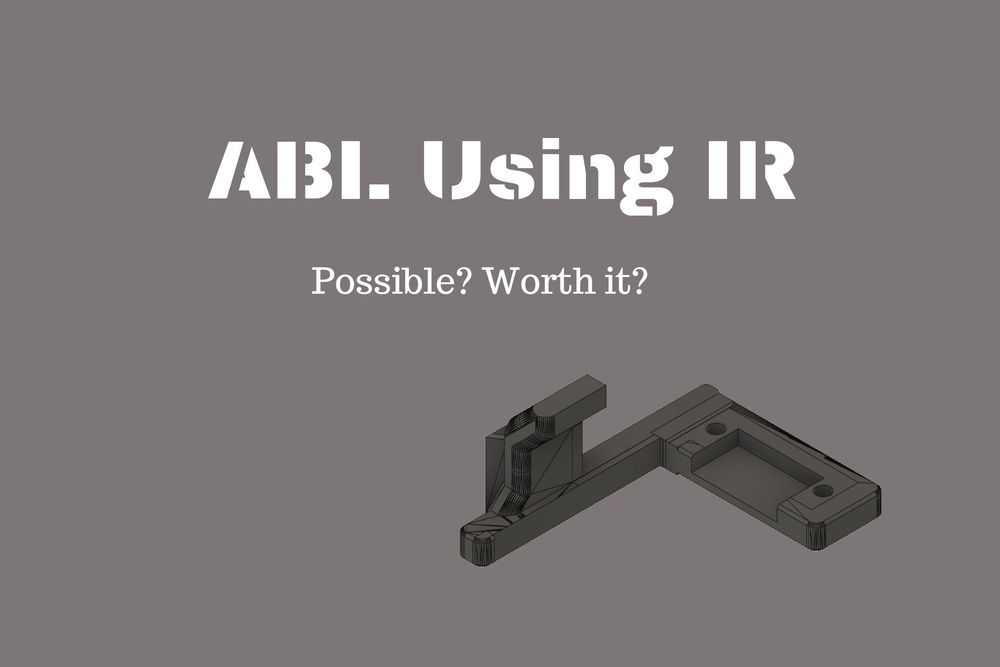
ABL Using IR
In my previous post, I wrote a thrifty solution to achieving Auto Bed Levelling on Ender 3 using the work of thingverse user stevohen. If you tried it out, you would realise that It is a semi-automatic method and requires you to slide the switch in and out of the mount everytime you start a print. This is mostly fine for regular use. However, if you are experimenting with some settings on cura or designing a model and end up cancelling the print every now and then they fail, you are going to get frustrated with sliding the switch every 5 minutes. This is what happened to me and I started trying out other methods to completely automate the entire auto bed levelling process. Being the Thrifty Engineer that I am, I would much rather try to accomplish this with existing things in my store. By store, I mean the dump I made with components salvaged from broken things.
Well, being the genius I am, I had the brilliant idea that I could just use an IR Sensor that was lying around. And since this thing costs barely INR 70 or about $1, it's truly worthy of being here on ThriftyEngineer.com. In this post, I will show you how I managed to get complete auto bed levelling on my Ender 3 (Well with some caveats of course). Tag along and feel free to comment or ping me if you have any queries.
When I started researching on this topic online, I found out that this was pretty much never done before. Or at least never been documented. No blogs, no youtube videos, nothing. I was quite baffled as this seemed to be a very very low cost and simple way to solve this bed levelling issue. It was only after completing everything did I realise the reason why no one uses these IR Sensors for Auto Bed Levelling. Nonetheless, it still is technically possible to use them. And to give you a very short answer, it has too many issues and is not worth it. If you wish to understand exactly what goes wrong and some of my solutions to solve them, please read along.
Pre-Requisites:
- Ender 3 with bootloader flashed.
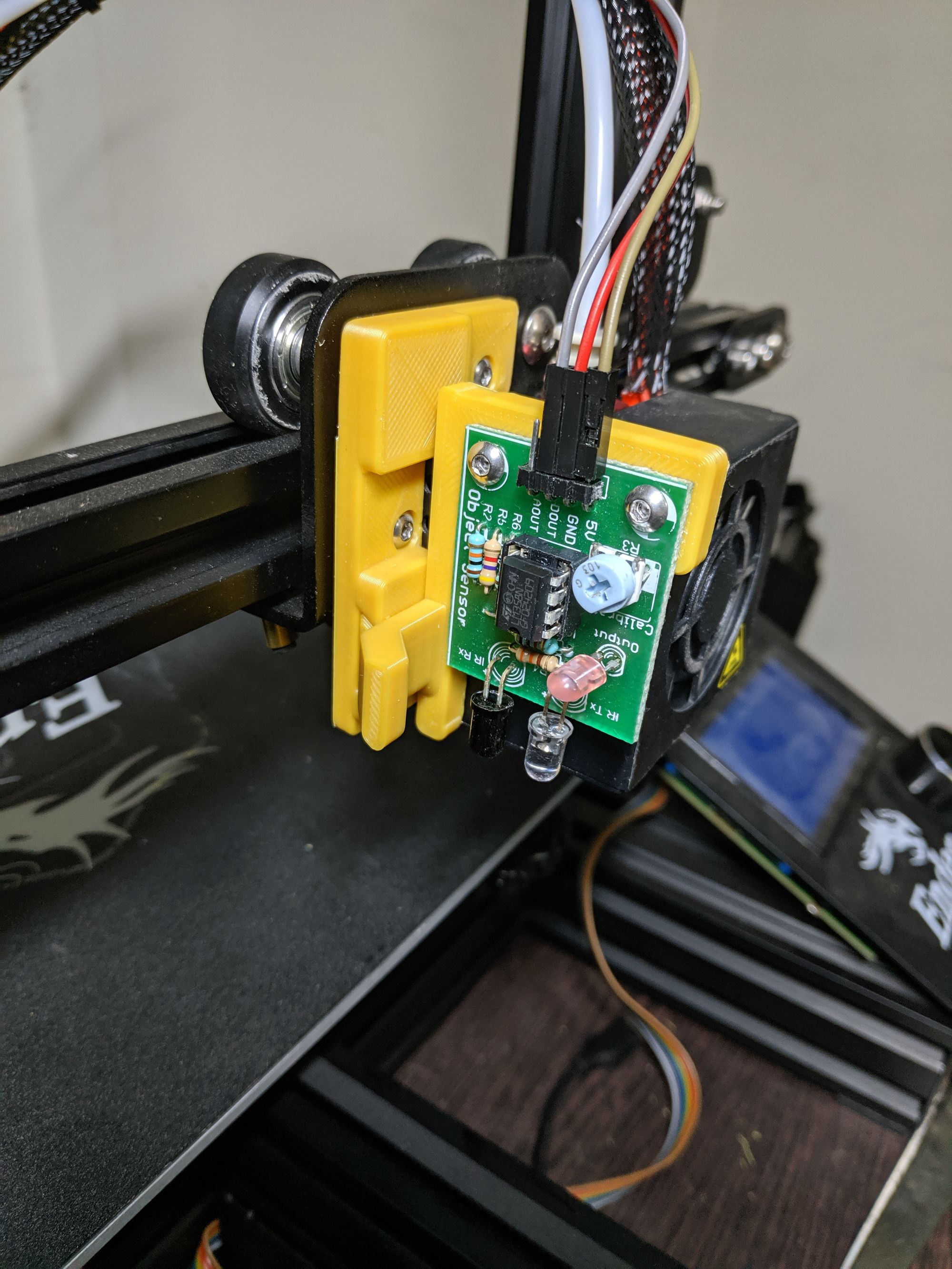
- IR Sensor like one shown below.
- Some 3D modelling skills in SketchUp or Fusion 360.
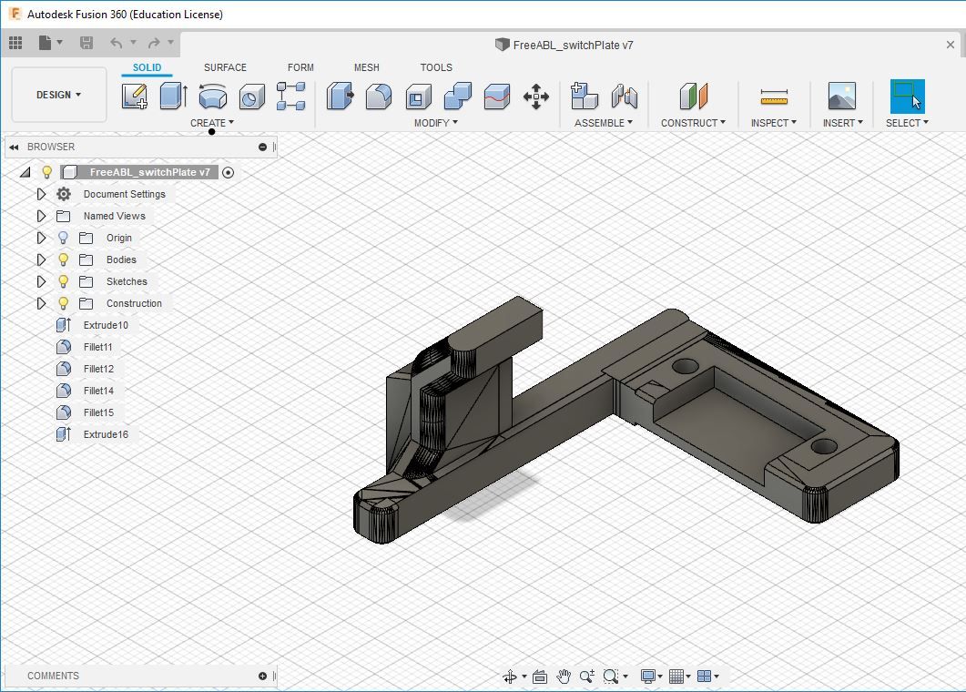
What you see in the picture above is my IR Sensor mounted on my final model of switch plate. I remodelled the switch plate from FreeABL to suit the particular IR Sensor I had. From what I have seen online, there are a lot of different kinds of these IR Sensors and you will have to design or remodel the plate on your own. I will share my model if it helps you.
Here's how you get started.
Part 1: Physical Mount
- As explained above, you need to model and print the adapter plate to suit your sensor. It will look something like this:
- A few things to consider when you (re)model:
- The distance between the screws.
- How far from the handle should your first screw be so that it won't obstruct the IR Sensor module when you try to screw it in.
- The depression you might have to give so that the soldered parts do not get obstructed by the plastic.
- In my case, I already had the FreeABL mount. So I just adapted the same to fit under my IR Sensor. It took me about 2 trials to get what I wanted correctly.
Part 2: Wiring
This is where things got quite interesting. The Z axis end stop switch is a very basic switch and has only 2 wires. One being signal and the other being voltage high. The IR Sensor is going to need three wires minimum. Along with the above two, it also needs a dedicated ground wire. To overcome this without any splicing of wires or any extra circuitry, I decided to use the IO pins in my Ender 3's melzi board to power the sensor. And then connected the digital out to the signal wire on the end stop's signal wire. I will try and make a simple diagram for you when I get some more time.
Part 3: Firmware
The firmware needs to be modified exactly the same way it had to be modified to use FreeABL. Here are the settings I changed.
You need to have these the lines to reduce space on the default sanguino board. If you have a board like SKR 1.4 or MKS Gen L, you may skip these as they have more space.
#define SLIM_LCD_MENUS
//#define SHOW_BOOTSCREEN
//#define SPEAKER
These lines enable auto bed leveling:
#define FIX_MOUNTED_PROBE
#define AUTO_BED_LEVELING_BILINEAR
#define Z_SAFE_HOMING
#define Z_MIN_PROBE_REPEATABILITY_TEST
#define EXTRAPOLATE_BEYOND_GRID
These lines tell the firmware where the probe is relative to the front left corner of the heat block, so that when probing happens the printer will treat the probe as the center. The values I have here are not perfect, but they work close enough for me. You will most probably only need to adjust the "Make the following changes: ". This can also be adjusted later and is a topic by itself.
#define X_PROBE_OFFSET_FROM_EXTRUDER -37 // X offset: -left +right [of the nozzle]
#define Y_PROBE_OFFSET_FROM_EXTRUDER -5 // Y offset: -front +behind [the nozzle]
#define Z_PROBE_OFFSET_FROM_EXTRUDER -5 // Z offset: -below +above [the nozzle]
NOTE: The next definition occurs 3 times in the file. Change the one that occurs right after the AUTO_BED_LEVELING_BILINEAR "#if" statement. This line will change the default mesh grid to 4x4 instead of 3x3. You can even make it 5 if you want. Increasing this will increase the accuracy of the bed levelling but take more time to complete the bed levelling process. You will need to change this to a higher number only if you have an wxtremely warped bed. Otherwise it won't make too much of a difference!
#define GRID_MAX_POINTS_X 4
You may also change these optionally. They just give you a few more options in your menu screen.
For fun! Change the name of your 3D printer on the home menu:
#define CUSTOM_MACHINE_NAME "Ravi's 3D"
In file Configuration_adv.h
This line is also necessary to reduce program size. Again, you do this if you have the original board. If you have an after market board like SKR 1.4 or MKS Gen L.
//#define ARC_SUPPORT // Disable this feature to save ~3226 bytes
You may refer my FreeABL Guide to get a more detailed picture of what is being done in those lines.
Part 4: Initial Setup
For the first run, push you gantry up and send command G28 to auto home. When the gantry starts to move downwards, put your hand under the sensor to trigger the sensor. This is important and will help you avoid the nozzle ramming into your bed. Depending on how your machine responds, you may need to adjust the sensitivity of the sensor and also invert the z axis bool in the firmware. Post this, run command G29 L30 R190 F30 B190 to perform auto bed levelling routine.
Now this is where I realised why this sensor was not more popular with the 3D printing community for auto bed levelling. You see, when the bed does not have uniform colour and has any sort of differences in reflectivity, the sensor's trigger goes haywire. What do I mean? Well, every where my bed had the Creality logo, the sensor could detect from about 40 mm. However, on the black surface area, it could only detect from 8 mm with the exact same sensitivity settings on the potentiometer. Why? The logo area was reflecting much better than the black area.
So what's the solution? Simple. This. It is uniformly black and thus gives a very good reflective surface. However, if you are going to pay that much, you might as well by an NPN or PNP inductive sensor like this or this one.
I would also like to let you know that the IR Sensor is extremely sensiive to sunlight. And the height at which it detects varies widely. So if you wanna still use this simple sensor, you need to completely isolate the machine or sensor from external light sources.
All in all it's not worth it.
Well, now you know why the IR Sensors are not popular or probably even used in the 3D Printing community. If you do have a better way to do auto bed levelling the Thrifty Engineer style, please do comment and let me know.