ABL under 10$ for Ender 3 (With klipper config)
A while ago, I wrote this article that helped with semi-auto bed levelling for the ender 3. The frustrating part with this method is that, while free, it requires manual work every time you need to home the device.
If you are willing to spend about Rs 200 (or up to $10 outside India), you can get this servo and make a pretty good auto bed levelling system using ABL from here. Being a contact-based probe, it works well on all kinds of beds.
Prerequisites:
- A servo motor and a switch (or this).
- Print out these parts. There are variants for Hero Me fan duct and for a micro swiss hot end. Choose appropriately.
- 6 meters of copper wire
- A soldering kit.
How To:
1. Hardware
- Measure the length of wire required from the mainboard to the hot end.
- Cut five pieces of wire for the measured length.
- Solder two wires to the microswitch.
- Extend the wires from the servo as well. You can use either dupont cables or splice them.
- Mark the extended wires with a permanent marker for later. (You can mark one bar on both ends of a wire, 2 on either sides of the second etc.
- Once this is done, pass the extension cables through the sheathing.
- Connect the endstop wires to Z end stop cable. If you have a 2 pin switch, the order doesn't matter. On the other hand, if you are using the 3 pin switch, you wanna connect one wire to common and the other to either normally open or normally closed. (Shortened to NO and NC respectively.) I prefer normally open. You will have to contact your seller if this information isn't mentioned on the website or on the switch.
- If your switch is bigger or smaller than the printed arm, you can just use your pliers and use instant glue to hold the switch in place.
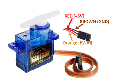
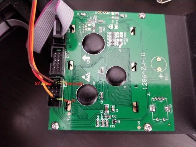
- Once you are done with that, you need to connect up the servo. A servo has 3 wires. One of them is a live wire you need to connect to 5v, another to neutral and the third is the signal wire (PWM). In my case, red was 5v, brown was ground and orange was PWM. Like the image shown below.
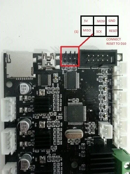
10. I used the IO pins from the stock ender 3 board to supply power. Below is an image that shows the IO pin out diagram from all3dp. Connect the 5v and GND wires to their respective pins. You can use a female dupont wire to make it a bit easier.
Edit: You can also use the expansion pins on your LCD for power. Look at the pic under point 11's edit.
- For the signal wire, you have two options.
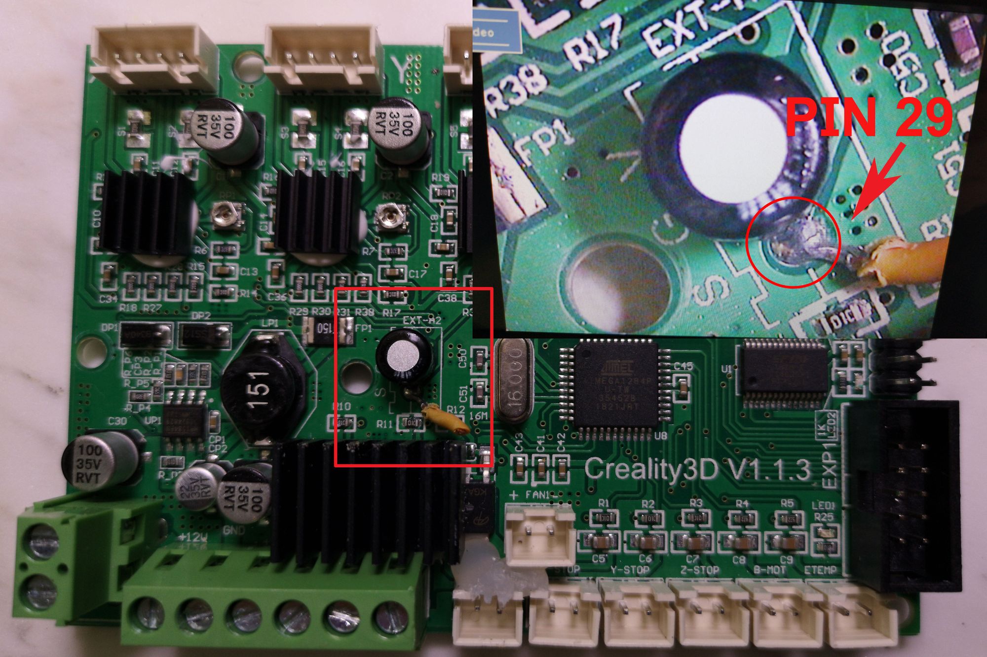
The first is to splice the speaker wire (pin 27) from the cable that goes to your display and connect your signal wire to it. You may also get an adapter if you do not wish to damage your cable.Second is to find and solder a wire to an unused pin (pin 29) on the board. Pick this method only if you are confident about your soldering skills as the point is very close to a capacitor and quite easy to damage it. Below is an image to show you where the pin is.
Edit: There is a better way if you are willing to lose the speaker. Scroll through.
Edit: I recently found this. It turns out the expansion pins on the LCD can be used for both power and signal. I will include a pic from the same thing. Credit to thingiverse user torsoreaper for this.
If you wish to keep the pin for speaker, you may still use pin 29. You can also use the other pin for a filament run out sensor or other goodies. I used the second method of soldering to pin 29 though. Pick your poison. Your config changes based on which one you choose.
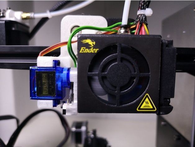
12. Screw the servo to the holder, fix or glue the switch to the arm, place the single lever that came with your servo in the slot and screw the arm to the servo. Fix the entire thing to your printer.
2. Software
2a. Marlin
If you are using marlin, you need to make these changes in your firmware.
- Enable or change these settings in Configuration.h
#define Z_MIN_PROBE_USES_Z_MIN_ENDSTOP_PIN
#define Z_ENDSTOP_SERVO_NR 0
#define Z_SERVO_ANGLES {174,45}
#define Z_HOMING_HEIGHT 2
#define Z_CLEARANCE_DEPLOY_PROBE 6
#define Z_CLEARANCE_BETWEEN_PROBES 6
#define Z_MIN_PROBE_REPEATABILITY_TEST
#define AUTO_BED_LEVELING_BILINEAR
#define EXTRAPOLATE_BEYOND_GRID
#define Z_SAFE_HOMING
#define HOMING_FEEDRATE_Z (6*60)
#define SERVO_DELAY { 1000 }
#define DEACTIVATE_SERVOS_AFTER_MOVE - Set up the offset
#define X_PROBE_OFFSET_FROM_EXTRUDER -36 // X offset: -left +right [of the nozzle]
#define Y_PROBE_OFFSET_FROM_EXTRUDER -5 // Y offset: -front +behind [the nozzle]
#define Z_PROBE_OFFSET_FROM_EXTRUDER 0 // Z offset: -below +above [the nozzle] - Select Servo pin, under the Servo section in Configuration.h, add these lines.
For Pin 27 (using Pin 27 adapter or cutting the lcd wire or using expansion of LCD)
#define SERVO0_PIN 27
#define NUM_SERVOS 1
For Pin 29 (Soldering the servo wire to the board)
#define SERVO0_PIN 29
#define NUM_SERVOS 1 - Optional Depending on your switch, you may have to invert it in the config.
#define Z_MIN_ENDSTOP_INVERTING true // set to true to
#define Z_MIN_PROBE_ENDSTOP_INVERTING true // set to true to invert the logic of the probe. - If you compile the sketch, you will get an error as the 1248p does not have enough space. So you need to disable the following features by commenting them out. (//)
Configuration.h
//#define SHOW_BOOTSCREEN
//enable this to gain some space.
#define SLIM_LCD_MENUS
Configuartion_adv.h
//#define ARC_SUPPORT // Disable this feature to save ~3226 bytes - Compile the sketch and Upload the firmware.
Setting Up
- Power up the printer and send
M280 P0 S90to the printer using pronterface. - If the arm moves, it is working.
- Send
M280 P0 S45, this is the stow position you can set it to any number. - Send
M280 P0 S174, check if the micro switch is parallel to the bed. adjust the S??? till it does. - Play around with the angles and determine the optimal stow and deploy angles. Once you are satisfied, note the two values.
- Change the angles in Configuration.h here
#define Z_SERVO_ANGLES {174,45} - Compile and upload the firmware.
Testing
- With the USB plugged into your Printer, send
M119(end stop status) on the terminal. You should get SENT: M119 READ: Reporting endstop status READ: x_min: open READ: y_min: open READ: z_min: open READ: ok . Your z_min must be open. - Push the z switch with your finger and send the same command again. z_min must now show "TRIGGERED". If it doesn't, there is an issue with your end stop wiring or your switch.
- If the open and triggered statuses or opposite, i.e., it shows triggered when open and vice versa, change the setting in step 4 in Configuration.h settings.
- If all is as expected, deploy the probe and check to see if the hot end is higher than the probe, else the hot end will hit the bed and the switch never trigger.
- If the last step is ok, send
G28to home the printer. It should home X, Y, then deploy the probe to home Z. Make sure the bed is clear. - Send
G29to probe the bed. - Send M500 to save to EEPROM or Add
G29as the start script of your slicer, so it will level the bed before every print.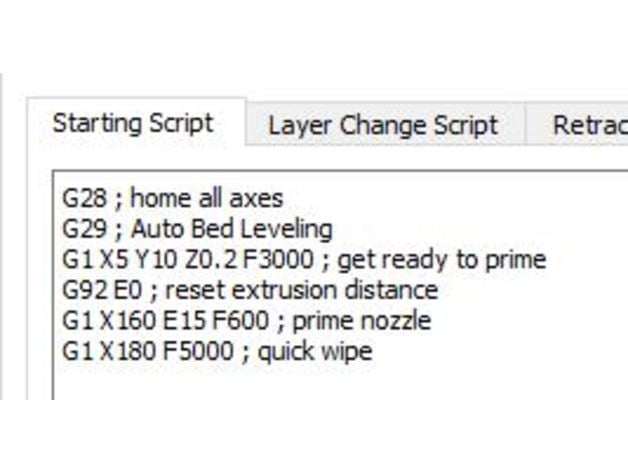
- Set your print to Z-probe-offset screen and turn the knob while you print a 1 layer STL. Till you get a good squished first layer.
- Understating the Z offset can be confusing. But it is quite simple. The '+' or '-' sign indicates whether the switch is above the nozzle or below. In this case, it is below. If you use something like the npn sensor, it will be above. So we use '-'. The number without the sign is the distance between the switch and the nozzle. If you want the nozzle to squish more, increase the absolute number. If it's too close to the bed, reduce it. Think of it this way. You set the Z offset to -10. Which means you are telling the printer that when the endstop triggers, the nozzle is exactly 10 mm above the bed. So, when you tell the printer to move nozzle to 0, it will move 10 mm down. Let's say the nozzle is too high. So need it to move more to reach the bed. You then increase the absolute number by 1 mm and your Z offset becomes -11 mm. Similarly, if you were using npn sensor and the offset was positive, you would increase the value from 10 mm to 11.
2b. Klipper
If you use Klipper, I recommend you to look at my config file here.
Here is what I modified on the stock config
Added the following code
[probe]
pin: ^!PC4
# Pin connected to the BLTouch sensor pin. This parameter must be
# provided.
# control_pin: PA4
# Pin connected to the BLTouch control pin. This parameter must be
# provided.
x_offset: -37.00
y_offset: -5.00
z_offset: 11.15
speed: 5.0
samples: 1
#   The number of times to probe each point. The probed z-values will
#   be averaged. The default is to probe 1 time.
#sample_retract_dist: 3.0
#   The distance (in mm) to lift the toolhead between each sample (if
#   sampling more than once). The default is 2mm.
#samples_result: average
#   The calculation method when sampling more than once - either
#   "median" or "average". The default is average.
[servo bltouch]
pin: PA2
#   PWM output pin controlling the servo. This parameter must be
#   provided.
maximum_servo_angle: 180
#   The maximum angle (in degrees) that this servo can be set to. The
#   default is 180 degrees.
minimum_pulse_width: 0.0005
#   The minimum pulse width time (in seconds). This should correspond
#   with an angle of 0 degrees. The default is 0.001 seconds.
maximum_pulse_width: 0.003
#   The maximum pulse width time (in seconds). This should correspond
#   with an angle of maximum_servo_angle. The default is 0.002
#   seconds.
initial_angle: 60
#   Initial angle to set the servo to when the mcu resets.  Must be between
#   0 and maximum_servo_angle  This parameter is optional.  If both
#   initial_angle and initial_pulse_width are set initial_angle will be used.
#initial_pulse_width: 0.0015
#   Initial pulse width time (in seconds) to set the servo to when
#   the mcu resets.  Must be between minimum_pulse_width and maximum_pulse_width.
#   This parameter is optional.  If both initial_angle and initial_pulse_width
#   are set initial_angle will be used
enable: True
#   Enable or disable servo. It can be enabled or disabled later using
#   SET_SERVO SERVO=my_servo ENABLE=<0|1> g-command. The default is True (=enabled)
[bed_mesh]

speed: 150
horizontal_move_z: 16
mesh_pps: 2,2
# samples: 2
# sample_retract_dist: 5
mesh_min: 28,30
mesh_max: 198,198
probe_count: 3,3
There are 2 pins here. And this is what you need to pay attention to.
Pin under [probe] is the endstop pin. Do not change it.
Pin under [servo bltouch] is the one that represents either pin 27 (spliced speaker wire/adapter/expansion one) or pin29 (the one you soldered and nearly burnt the capacitor next to it)
Depending on which pin you chose, use the below values
Pin 27: PA4
Pin 29: PA2
I also added the following macros to override homing. This is required to deploy and stow the switch as and when required.
[homing_override]
set_position_z: 20
axes: z
gcode:
       SET_SERVO SERVO=bltouch ENABLE=1
       SET_SERVO SERVO=bltouch ANGLE=60
       SET_SERVO SERVO=bltouch ENABLE=0
       G92 Z0
       G90
       G1 Z20 F600
       G28 X Y
       G1 X123 Y117 F6000
       SET_SERVO SERVO=bltouch ENABLE=1
       SET_SERVO SERVO=bltouch ANGLE=134
       G4 P500
       SET_SERVO SERVO=bltouch ENABLE=0
       G28 Z0
       G1 Z20
       SET_SERVO SERVO=bltouch ENABLE=1
       SET_SERVO SERVO=bltouch ANGLE=60
       G4 P500
       SET_SERVO SERVO=bltouch ENABLE=0
[gcode_macro G29]
gcode:
       ; G28
       G1 Z20
       G4 P400
       SET_SERVO SERVO=bltouch ENABLE=1
       SET_SERVO SERVO=bltouch ANGLE=134
       G4 P500
       SET_SERVO SERVO=bltouch ENABLE=0
       BED_MESH_CALIBRATE
       SET_SERVO SERVO=bltouch ENABLE=1
       SET_SERVO SERVO=bltouch ANGLE=60
       G4 P500
       SET_SERVO SERVO=bltouch ENABLE=0
Conclusion and Credits
This is a time consuming upgrade. Well worth it though. While I have been using this for nearly an year now, I would still recommend you to go for an npn proximity sensor like this or this. The only reason I did not go with them is that they are rated 6 to 36v and I would need a buck converter. However, quite a few people have claimed they work with 5v as well. This is a hit or miss.
Hope this guide was useful to you. Feel free to drop a comment if you need help or have suggestions. Make sure to check out my other posts and the original thingiverse pages for the ABL system as well as the expansion find .


